442 Results
View results:
Sort by:
A network dongle is the appropriate solution to ensure security for licensing within companies working with several RFEM and/or RSTAB licenses. First, the dongle is placed on a central server. The licenses are then requested by RFEM and RSTAB, as well as all other stand-alone programs, from this dongle via the network.

In RFEM, you have the option to create and analyze cables using sheaves. For this, use the "Cable on Pulleys" member type. It is ideal for pulley systems, where the longitudinal forces are transferred via sheaves.
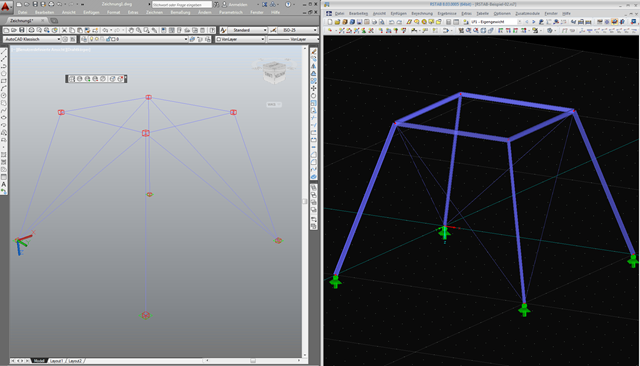
As requested by many customers, the nodes are now represented by cubes after export using the direct interface to AutoCAD or in a DXF file. If you want to reuse the AutoCAD data in RFEM or RSTAB, make sure not to import all the layers when specifying the settings for the import.
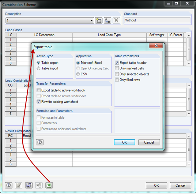
In RFEM and RSTAB, you can create a combination scheme in the combinatorics of load cases and combinations. This scheme can be used for other projects by transferring it to other computers using the Export/Import function. Thus, multiple people working on a project can use the same scheme.
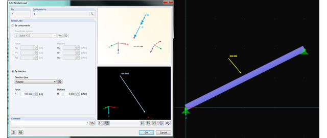
In RFEM and RSTAB, you can now rotate nodal loads or apply them on member axes. Thus, inclined members can also be loaded with nodal loads perpendicularly or along the member axis.
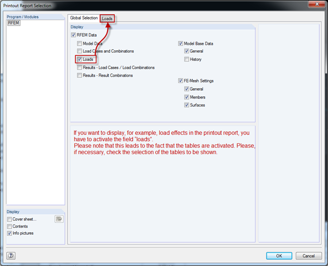
RFEM version 5.04.xx includes an adjustment when printing graphics in the printout report. In order to display graphics in the printout report, you have to select the respective check boxes in the Global Selection tab of the Printout Report Selection window (see the figure). Checking the boxes unlocks the corresponding tabs for the tables. where you can select the tables to be displayed.
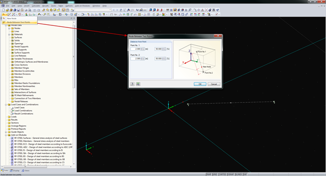
In RFEM and RSTAB, you can create nodes not only by means of coordinates, but also by means of existing nodes. You can use the "Node Between Two Points" function to create a node located on an imaginary line connecting two nodes. You can enter the distance as a percentage or according to the relative lengths.
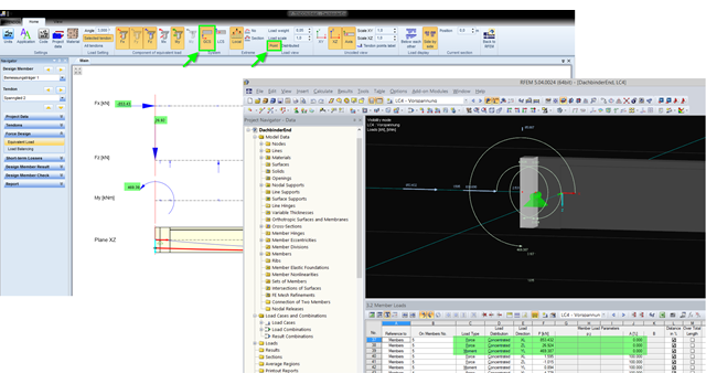
The equivalent loads determined in RF-TENDON due to prestress are transferred in RFEM as member loads or as line loads. A member load is used for member types with their own stiffness; a line load is used for member types without their own stiffness. In order to understand which values of the concentrated loads are to be transferred from RF‑TENDON to RFEM, you should use the following display settings: ~ Reference of the loads to the global coordinate system (GCS), ~ Load display: "Point"
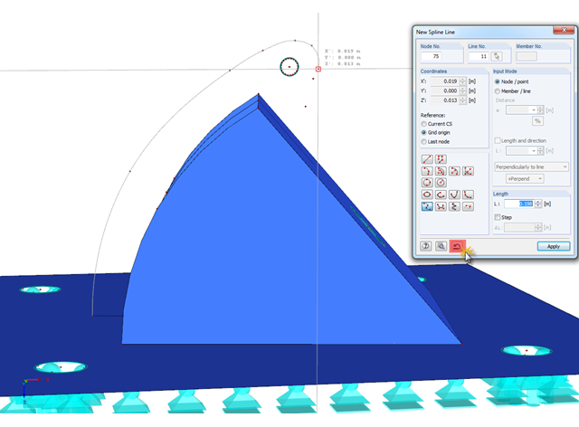
In RFEM, if you want to display a curved geometry (preferably in one continuous line), you can use splines or NURBS, for example. When modeling, you should pick the individual nodes one after another. If a mistake is made, you can go back using the special Undo function in the "New Spline Line" window. Thus, it is not necessary to enter the entire continuous line again.
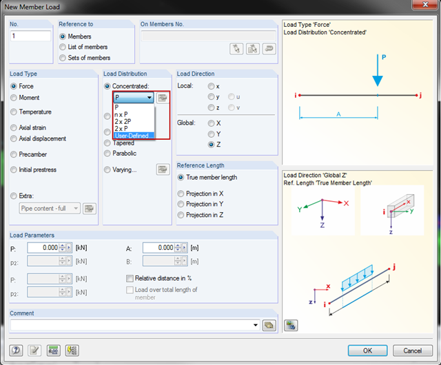
You can now also create concentrated member and line loads in RFEM and RSTAB. This is an extension of the original member/line load function. From now on, you can create several concentrated loads with uniform or user-defined load distribution on a member or a line.
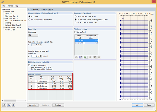
With the RFEM 5.04.0024 and RSTAB 8.04.0024 versions, you can define the antenna ice loads in RF‑/TOWER Loading. The program provides the values from the manufacturer databases. In addition, you can define the ice loads manually or use the calculation based on simplified geometry.

The new RF‑/DYNAM Pro - Natural Vibrations module has been available since RFEM version 5.04.xx and RSTAB version 8.04.xx were released. Masses can now be imported directly from load cases and load combinations.
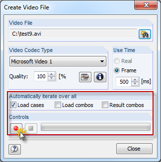
In RFEM and RSTAB, you can now create a video file of the results of all load cases, load combinations, and result combinations. Thus, you can very easily create a visual presentation of a moving load crossing a bridge, for example. This function is available under "Tools" → "Create Video File".
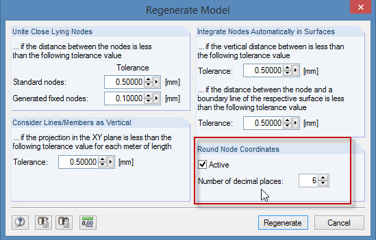
During the cooperation between the structural and design engineers, the DXF format is often used if there is no direct interface. However, the geometrical data of these DXF files are not always accurate. For example, an inaccuracy in the third decimal place is not noticeable, but it can lead to numerical problems when generating the FE mesh in RFEM.
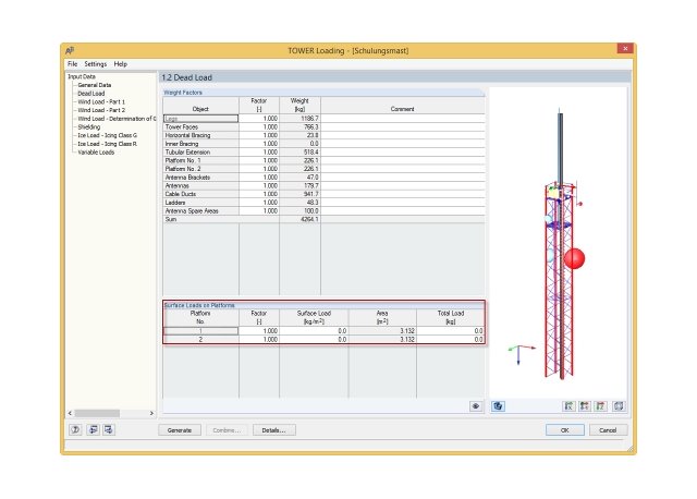
In the RFEM 5.04.0024 and RSTAB 8.04.0024 versions, there is a new feature in RF‑/TOWER Loading that allows you to define additional surface loads in a load case for dead loads; for example, from grids on platforms.
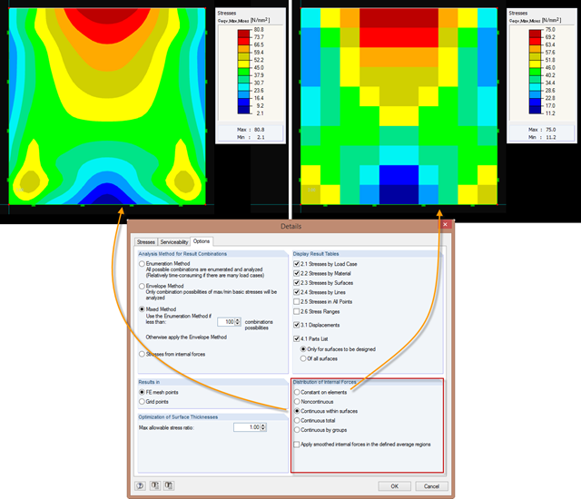
Just as in the RFEM Display Navigator, you can set the distribution of internal forces in surfaces in RF‑STEEL Surfaces. Since deformations are always the result of the FEM calculation, the corresponding forces will be recalculated. This means that the internal forces on an FEM element are calculated depending on the composition (triangular or square) in three or four places. In order to obtain continuous internal forces and thus a smoothed distribution, these internal forces have to be interpolated. Interpolation is done by selecting the "Distribution of internal forces" option in the surfaces.
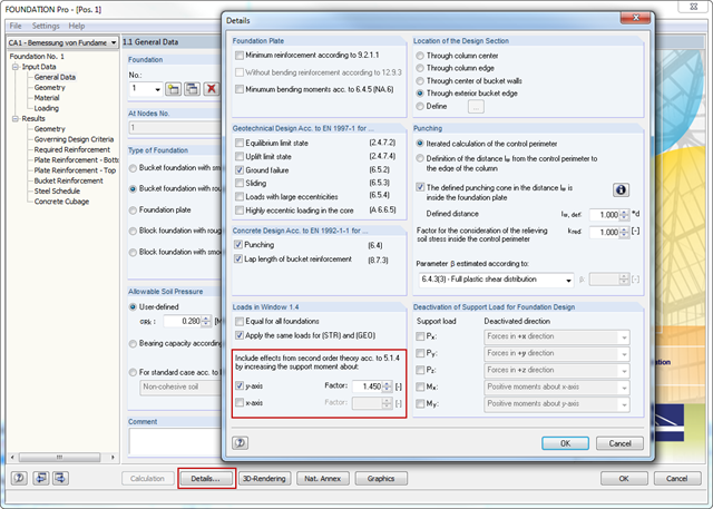
In RFEM and RSTAB, the internal forces of individual load combinations are determined according to the second-order analysis by default. If you use the RF‑CONCRETE add‑on module for stability analysis of reinforced concrete columns, you can change the calculation method of LCs to the linear static analysis, since the effects of the second‑order analysis are already considered in the calculation according to the model column method in RF‑CONCRETE Columns (nominal curvature method).
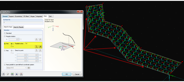
It is often necessary to adjust the FE mesh of surface elements to the geometric structure. RFEM provides various options for this. For example, the FE axis can be rotated around a point, aligned in the direction of a point, or oriented to a user-defined coordinate system. Another option is the direction parallel to a line, and in this case in particular, it is possible to enter or select several lines.
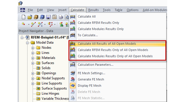
In RFEM and RSTAB, files can be computed automatically in a sequence of calculation, so the models can be processed overnight, for example.
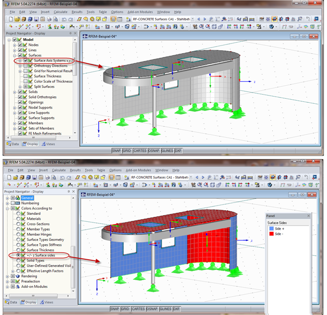
When calculating the surface reinforcement in RF-CONCRETE Surfaces, the result values for both surface sides +/- z are available. If you are unsure which side of a surface is the positive or the negative z side, you can hide the local coordinate system of each surface in the RFEM Project Navigator - Display under "Model" → "Surfaces" → "Surface Axis Systems x,y,z". In the case of complex structures, this can quickly become confusing. Displaying multiple axis systems makes it difficult to recognize the incorrect direction of a surface, for example (see the figure on the top).
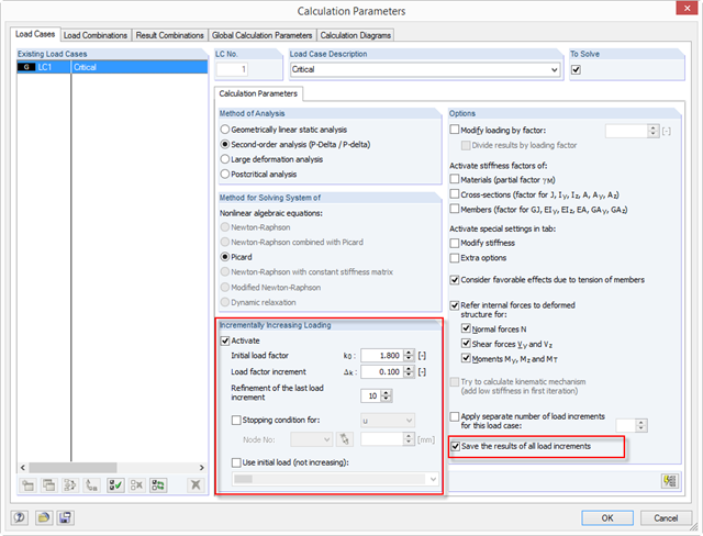
With RFEM 5.04, there are new options for the system analysis (critical load factors) of load cases and load combinations in the calculation parameters of the RF‑STABILITY add‑on module: ~ The load increment is not closed due to stability problems, but optionally also due to predetermined deformation limits. ~ The calculation method is applicable to all nonlinear calculations. ~ You can define an initial load (LC/CO) that is not increased (for example, self-weight). ~ The "Refinement of the last load increment" option provides an efficient option to determine the critical load factor as precisely as possible.
When calculating the surface reinforcement in RF-CONCRETE Surfaces, the result values for both surface sides +/- z are available. A previous post describes how to display the local surface sides in RFEM.
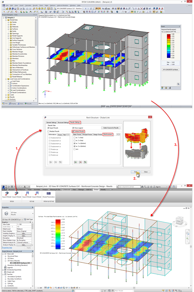
The interface between RFEM/RSTAB and Autodesk Revit has been improved: You can now transfer results from RFEM/RSTAB to Revit and display them there graphically. This option is available in a new tab when importing a file.
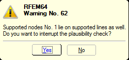
You can define nonlinear supports in RFEM and RSTAB. In RFEM, these are represented by nodal, line, and surface supports. Many customers contact us because of nonlinearities that are apparently not acting as desired. For example, there is a failing line support in a model. Since the structure is statically determined as supported, a linear nodal support is usually added. If the nodal support rests at the start or the end of a nonlinearly supported line, there is no clear definition of the degrees of freedom, so the nonlinearity cannot be considered properly. In this case, RFEM displays a warning message.
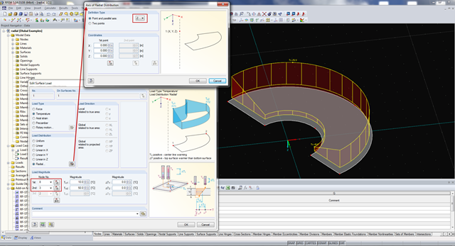
A new direction for temperature load is available in RFEM. Now, it is also possible to apply temperature loads with radial load distribution on a structure. The load is defined using an outer and an inner node, and an axis around which the radial load is applied.
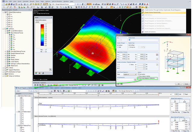
For evaluating results on surfaces, RFEM provides the option to define sections. Basically, two different types of sections are available. One, the creation of a temporary section showing the result diagrams of the desired cutting edge only once; the other, the definition of a section in the dialog box, which is then created as a separate object in RFEM, and thus the results can be viewed at any time. Displaying the results of defined sections is done graphically in RFEM, but they can also be displayed separately in a dialog box and be included in the printout report.
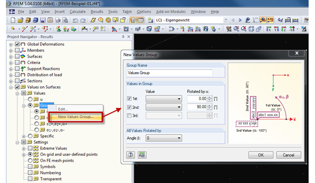
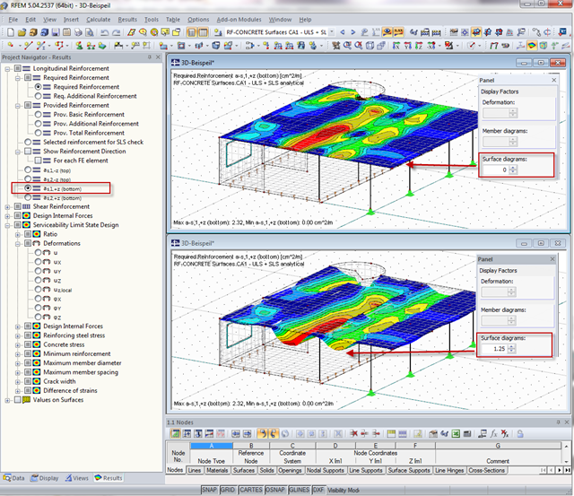
RFEM provides the option to display up to three result values of the surface results in each group. Four groups are preset under "Groups" in the Results Navigator.
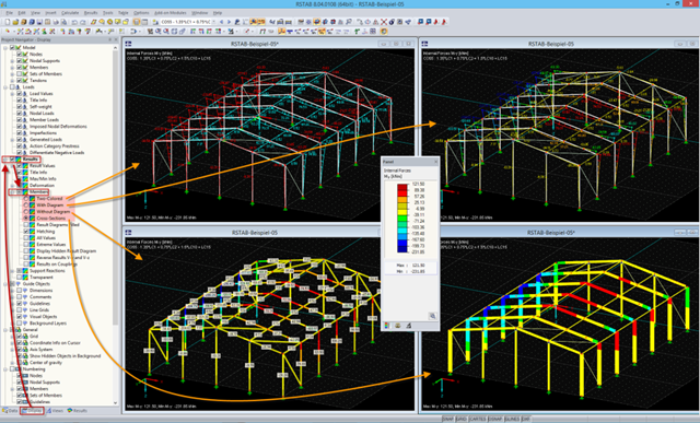
In the RFEM and RSTAB work window, four display modes are available for the results of members. They can be selected in the Display Navigator under "Results" → "Members".
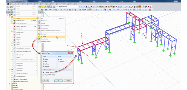
In RFEM and RSTAB, there are several ways to select a part of the structural model for further processing. The most frequently used selection option is definitely "selection using window". Depending on the size of the structure, the simultaneous selection of several areas of the structure using this option may be time-consuming, since the unwanted model parts are selected as well.
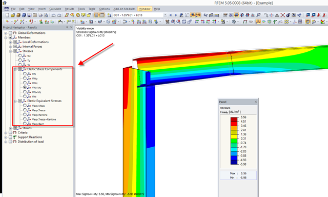
RFEM 5.04.xx allows for graphical visualization of normal and shear stress of members (this feature is available only if the RF‑STEEL add‑on module is licensed).